Doc:2.6/Manual/3D interaction/Navigating/3D View Options
View Shading
Mode: All modes
Hotkey: Z / ⇧ ShiftZ / AltZ / ⇧ ShiftAltZ / D
Description
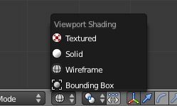
Depending on the speed of your computer, the complexity of your scene, and the type of work you are currently doing, you can switch between several drawing modes:
- Textured
- Displays UV image textured models with OpenGL lighting. Neither procedural textures or non UV-mapped textures will be shown.
- Shaded
- Approximates all textures and lighting at each vertex, and blends from one to the next. Much less accurate than using the render engine to check textures, but much faster. Note that if you have no lighting in your scene, everything will remain black.
- Solid
- This is the default drawing mode where surfaces are drawn as solid colors, with built-in OpenGL lighting. This draw mode is not dependent on scene light sources and can be configured in the Solid OpenGL lights group of controls from the System & OpenGL tab of the User Preferences window.
- Wireframe
- Objects only consist of lines that make their shapes recognizable (e.g. the edges of meshes or surfaces…).
- Bounding Box
- Objects aren’t drawn at all. Instead, this mode shows only the rectangular boxes that correspond to each object’s size and shape.
You can switch between these draw modes by:
- Using the Draw type drop-down list in the 3D views’ header (see A 3D view’s draw mode button).
- Pressing D to pop-up the Draw mode menu.
- Using the Z-based shortcuts as detailed below:
| Z | Switches between Wireframe and Solid draw modes. |
| ⇧ ShiftZ | Switches between Wireframe and Shaded draw modes. |
| AltZ | Switches between Solid and Textured draw modes. |
| ⇧ ShiftAltZ | Switches to the Textured draw mode. |
View Properties Panel
Mode: All modes
Panel: View Properties
Menu: View » View Properties...
Description
In addition to the header controls described above, the View Properties panel lets you set other settings regarding the 3D view. You show it with the View » View Properties... menu entry.
View
- Lens
- Control the focal length of the 3d view camera in millimeters, unlike a rendering camera
- Lock to Object
- By entering the name of an object in the Object field, you lock your view to this object, i.e. it will always be at the center of the view (the only exception is the active camera view, 0 NumPad).
- If the locked object is an armature, you can further center the view on one of its bones by entering its name in the Bone field.
- Lock to Cursor
- Lock the center of the view to the position of the 3D cursor
- Lock Camera to View
- When in camera view, use this option to move the camera in 3D space, while continuing to remain in camera view.
- Clip Start and Clip End
- Adjust the minimum and maximum distances to be visible for the view-port.
Notice
To avoid this...
When perspective is disabled only the far Clip-End is used, very high values can still give artifacts. This is not specific to blender, all OpenGL/DirectX graphics applications have these same limitations. Examples: |
- Local Camera
- Active camera used in this view
- 3D Cursor Location
- Here you can precisely specify the position of the 3D cursor
Item
This section displays the currently selected object
Display
- Only Render
- Displays only items that will be rendered.
- Outline Selected
- If disabled, the pink outline around your selected objects in Solid/Shaded/Textured draw types will no longer be displayed.
- All Object Origins
- If enabled, the center dot of objects will always be visible, even for non-selected ones (by default, unselected centers might be hidden by geometry in solid/shaded/textured shadings…).
- Relationship Lines
- Controls whether the dashed parenting, constraining, hooking, etc., lines are drawn.
- All Edges
- When wire overlay is enabled in the Object context, this options forces all of the wireframe to be displayed in the viewport.
- Grid Floor
- If disabled, you have no grid in other views than the orthographic top/front/side ones.
- X Axis, Y Axis, Z Axis
- Control which axes are shown in other views than the orthographic top/front/side ones.
- Lines
- Controls the number of lines that make the grid in non-top/front/side orthographic views, in both directions.
- Scale
- Control the scale of the grid floor
- Subdivisions
- Controls the number of sub-lines that appear in each cell of the grid when you zoom in, so it is a setting specific to top/front/side orthographic views.
- Shading
- Control the way objects in the 3D view are shaded.
- Textured Solid
- Display face assigned textures in solid view.
- Toggle Quad View
- Toggles the four pane 3D view. Read more about arranging frames »
Background Image
Mode: All modes
Panel: Background Image
Menu: View » Properties...
A background picture in your 3D view is very helpful in many situations: modeling is obviously one, but it is also useful when painting (e.g. you can have reference pictures of faces when painting textures directly on your model…), or animation (when using a video as background), etc.
There are a few points worth to be noted about background images:
- They are specific to their window (i.e. you can have different backgrounds for each of your 3D views, e.g. top/front/side images for relevant views…).
- They are only available for Top, Side and Front (and their complementary versions) orthographic views! The picture remains the same when you switch between these six views.
- Their size is related to the window’s zooming factor (i.e. they grow big when you zoom in, etc.).
- You can use video files and animated sequences.
Settings
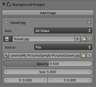
Blender manages this feature through the Background Image menu on the view properties panel (N). The option box at the top of this panel toggles the Background Image feature on/off. By default, there is only space for one image. The settings can be accessed by LMB ![]() the white triangle.
the white triangle.
Once enabled, you can add an image by selecting an existing datablock, or loading a new image. The Axis menu defines which views the image will appear in. Additional images can be added by LMB ![]() the Add Image button. When the image is loaded, the following settings become available.
the Add Image button. When the image is loaded, the following settings become available.
- Source
- Specifies what type of file is being used. Depending on the selected type, several options will appear below:
- File
- Use an image file
- Source File
- Represents the actual file that is linked to the current datablock. Supported formats include bmp, gif, jpg, png, tga, and tif.
- Source File
- Sequence
- a sequence of numbered image files
- Frames
- Set the number of image files to use in the sequence
- Start
- Sets the frame number to start on
- Offset
- Offsets the number of the frame used in the sequence
- Fields
- Sets the number of fields per rendered frame
- Auto Refresh
- Always refresh the image on frame changes
- Cyclic
- Cycle the images in the sequence
- Frames
- Movie
- Use a movie file:
- Match Movie Length
- Set the number of frames to match the movie
- Match Movie Length
- Generated
- Use a image generated in Blender:
- Width, Height
- Set the width and height if the image in pixels
- Blank
- Generates a blank image
- UV Grid
- Creates a grid for testing UV mappings
- Color Grid
- Creates a colored grid for testing UV mappings
- Width, Height
Opacity
- This slider controls the transparency of the background image (from 0.0 – fully opaque – to 1.0 – fully transparent).
Size
- Controls the size, or scale, of the picture in the 3D view (in Blender units). This is a scalar value so that width and height of the background image are each multiplied by the value to determine the size at which the background image is displayed. If one wishes to change the proportions of the image, it must be done in an impage processing program, such as GIMP.
X Offset, Y Offset
- The horizontal and vertical offset of the background image in the view (by default, it is centered on the origin), in Blender units.
| Use Lo-Res Proxy | |
| To improve PC performance when using background images you may have to use lower-resolution proxies. If your monitor resolution is 800×600, then the background image, full screen, without zooming, only needs to be 800×600. If your reference image is 2048×2048, then your computer is grinding away throwing away pixels. Try instead to take that 2k×2k image, and scale it down (using Blender, or Gimp) to, for example, 512×512. You will have sixteen times the performance, with no appreciable loss of quality or exactness. Then, as you refine your model, you can increase the resolution. |
Shortcuts


