「Doc:2.6/Manual/Animation/Techs/Armatures」の版間の差分
(→Animating Armatures) |
細 (1版 をインポートしました) |
(相違点なし)
| |
2018年6月29日 (金) 04:51時点における最新版
目次
Animating Armatures
Basically, animating armatures (aka rigs) is very similar to objects’ animation: for each bone, you define some key positions/rotations/scales, and use F-curves to interpolate between them. You should have read the rigging chapter before diving into this page (if you haven’t, follow the previous link)!
Armature animation is also known as “posing”, as one main technique is to define some key poses, and then blend between them with the NLA (or other high-level control tool). In Blender, it uses a specific Pose mode, which is heavily detailed in the third part of the rigging chapter.
Note that we won’t be able to deeply talk about armatures’ animation here. It’s a huge topic, and you should easily find many tutorials about it on the web! We will just try to give you a short intro to the some techniques available in Blender.
Basic Bones Animation
Basic bones animation is done in Pose mode. You can key each bone’s position (which is only useful for unconnected bones), size and rotation.
These F-curves (regrouped in the Pose set, in the Graph Editor window) control the bones in their local space, which means that they apply relatively to the armature object’s location/rotation/scale, but also relatively to the parent bones’ transformations – as you might expect!
Each bone will have its own Pose datablock of F-curves.
Otherwise, bones’ F-curves are nearly the same as transformation objects’ F-curves, except for the rotation.
Quaternions and Rotations
In Blender, bones are rotated in a four-dimensional space, which allows to use quaternions mathematics. Don’t bother if you don’t know them – it’s (hyper)complex, anyway! –, but this is why there are four F-curves for bones’ rotation, and why they are named X Quaternion Rotation, Y Quaternion Rotation, Z Quaternion Rotation and W Quaternion Rotation (the usual X/Y/Z axis, plus the forth W component).
You might ask yourself, why do they need to use quaternions? Well, first, they can ease maths (similarly to complex (or imaginary) numbers, in 2D geometry). But, more important for you, they allow a smoother interpolation in rotations when the bone is nearly aligned with one of its axis. Else, you would sometimes get strange, violent rotation movements…
But quaternions have a drawback: they are not directly usable by a human! So you should avoid to try to control bones’ rotations directly with their F-curves, unless you have a computer somewhere in your mind, the results will most of the time be unpredictable. Always use the 3D views and I key to insert/update your bones’ rotation keyframes.
Actions and NLA
Bones’ F-curves datablocks are always actions, which means you can edit them with the Action Editor mode of Dope Sheet Editor too – and obviously, create libraries of actions (movements) to be edited in the NLA Editor, or controlled with advanced tools like the Action constraint…
Pose Markers
Pose markers is another type of markers, that are specific only to the animating of armatures and shape keys and are used to denote poses in Action Editor (and animated shape keys as poses in Shape Keys Editor) mode of Dope Sheet editor.
Visualization
Pose markers show a diamond-shaped icon in Action Editor (and Shape Keys Editor) mode of Dope Sheet editor. See (Pose markers in the Action Editor mode of the Dope Sheet editor).
Adding Pose Markers
Pose markers are created automatically at the moment adding new pose in Pose Library. They are also created with respective tools in Action Editor (and Shape Keys Editor) mode of the Dope Sheet Editor.
Editing Pose Markers
As the editing are same for both Timeline and Pose markers, therefore see for details about editing markers here.
Using Pose Markers
For working with poses need to select name of Pose Library (or of Key Action for the shape keys) in Action data block of Dope Sheet header.
To see pose markers in Action editor (or Shape Keys Editor) mode of Dope Sheet editor click the menu Marker > Show Pose Markers. With this enabled, creating markers will add only pose markers in the Action Editor (or Shape Keys Editor)! With Show Pose Markers disabled, you may select and edit only timeline markers in the Action Editor (or Shape Keys Editor).
With the pose markers there are additionally available the selecting poses for movement their keyframes through the timeline in the Dope Sheet editor:
- Select > Between Selected Markers
- Select > Columns on Selected Markers.
Also, there are additionally possible to jump between yours poses with the pose markers:
- Marker > Jump to Previous Marker
- Marker > Jump to Next Marker
Indirect Bones Animation
As usual, you can also control your bones with indirect animation techniques. Apart from the standard ones (for example, you can obviously use drivers to control them…), they are two to be noted: Inverse Kinematics, and Constraints.
Note that you can also use bones oneself to control indirect animations. Think for example in the rotation of the forearm controlling a relative shape key’s influence, to make the muscles inflate when you bend the arm… And more generally, it’s often very hard to get nice deformations of meshes at the joints with just weighting (see the skinning part of the rigging chapter). Well, one way to solve this problem is to define relative shape keys for all the joints’ areas, modeling the mesh as it should be when fully bent, and control these RSK’s influence by the relevant bone’s rotations, through drivers!
Inverse Kinematics
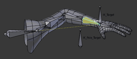
Also known as IK, this technique tries to ease your rig’s animation. The idea is to use (animate) only a target (which might be a bone, another Empty object, whatever…), and let Blender compute (with optional additional clues) the rotations of all bones in the chain controlled by the IK. For example, by just moving the foot bone, it can rotate (and optionally scale) the whole leg’s bones so that they follow this foot.
Inverse kinematics is very handy, but it can be quite hard to setup a correct IK system (i.e. avoid e.g. the knees to bend in the wrong direction!). You’ll find a full documentation about IK in the posing part of the rigging chapter.
Constraints
You can also add constraints to bones. This would for example allow you to restrict your bones’ rotations, or to have one bone stuck to another mesh object’s surface, etc. Note that:
- The rig’s rules are preeminent over bones’ constraints. In other words, a Copy Location constraint is only useful to unlinked bones, as it is their parents that control the position of linked bones!
- Bones have more spaces than objects, and their constraints can often be evaluated in all of them – this can produce very different results!
- There are at least two constraints specific to bones, the Inverse Kinematics and Spline IK ones.


